


")

- Actual version: MITCalc 1.75
- Producer: MITCalc - Ing. Miroslav Petele
- Basic description: MITCalc is a set of engineering, industrial, and technical calculations for your day-to-day routines. It will reliably, precisely, and most of all quickly guide you through the design of components, the solution of a technical problem, or a calculation of an engineering point without any significant need for expert knowledge.
- Language versions: EN, CZ, DE, SP, IT, FR, PT

Are you a mechanical engineer, design engineer, engineering draughtsman, technical employee, or a student at a college? Do you need to work with a professional computational system? But you are not willing or cannot pay thousands of dollars for inadequately complex or incomprehensible solutions? Then you may just need MITCalc.
MITCalc contains both design and check calculations of many common tasks, such as: spur gear, bevel gear, worm gear, planetary gearing, timing belt, v-belt and chain drives, bearings, springs, beam, buckling, plates, shells, shaft, bolt connection, shaft connection, force couplings of shafts, pins, tolerances, tolerance analysis, welded connection, technical formulas and many others. You also have available many material, comparison, and decision tables, including a system for the administration of resolved tasks.
MITCalc is an open system designed in Microsoft Excel to which you can make further modifications or user extensions without any programming skills.
You don’t have to learn MITCalc because you already know how to use it. The straightforward and fully comprehensive user interface with complex on-line help and the “expert notes” system will allow you to be more productive in just a few minutes.
MITCalc supports simple interconnection of individual parts between either each other, or your calculation, or tables. You can easily customize a solution to any special task you need.
MITCalc cooperates with many 2D and 3D CAD systems (AutoCAD, AutoCAD LT, IntelliCAD, Autodesk Inventor, SolidWorks, SolidEdge, Pro/Engineer...). To draw a designed solution in 2D or insert correspondent 3D models and their assemblies is a matter of seconds.
- Operating System: Microsoft Windows 8.1, Windows 7, Windows XP
- CPU: PIII 800Hz
- RAM: 256 MB
- Graphics card: 1024x768
- Other Requirements: Microsoft Excel 2000, XP, 2003, 2007, 2010
Do you think you may be interested in MITCalc and you would like to try it? You don’t need to wait! Download it right here (30-day evaluation). We truly believe that MITCalc will be a fundamental tool in everyday process of solving your technical tasks.
MITCalc Licensing
Individual license
The licence is possible to install and to activate to one computer only.
License protection
By software way
 The license protection is solved by software way.
MITCalc - Download
v 1.75 |
Mechanical, Industrial and Technical Calculations - Multilanguage version (EN,DE,FR,CZ,Chinese). Version for Excel 2007, 2010 (calculations saved as *.xlsb files) |
v 1.75 |
Mechanical, Industrial and Technical Calculations - Multilanguage version (EN,DE,FR,CZ,Chinese). Version for Excel 2000, XP, 2003, 2007 (calculations saved as *.xls files)
|
2D CAD support
Most of the calculations allow direct output to major 2D CAD systems. Just choose your CAD system in the calculation and select the desired view (a projection type). A drawing is then saved directly in the CAD system with the correct scale and system of layers.
Supported CAD systems at this time: DXF file, AutoCAD (12-2013...), AutoCAD LT(95-2013...), ZWCAD, Ashlar Graphite, TurboCAD...
User interface
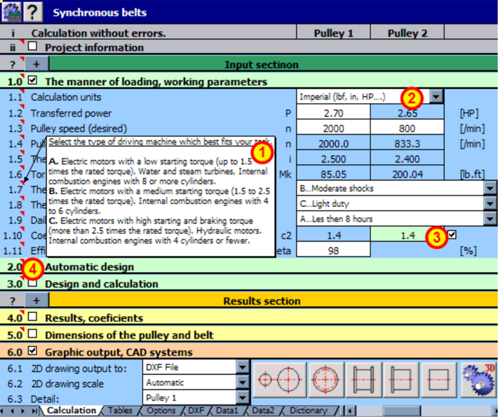
Most of the calculations have a similar user interface whose main advantage is its top-to-bottom layout – every task flows logically from an assignment to the results. In other words, the structure of a calculation is like what you are already accustomed to when solving the same task with a calculator and sheet of paper. Other advantages of our solution are:
- The “Expert Notes” system containing recommendations and tips for input and output values [1].
- Support of standard and imperial units [2].
- Recommended values – the calculation “knows” how to set (estimate) the right coefficients [3].
- Any change of parameters immediately results in recalculation of the entire task (a table).
- For most of the calculations, there is the “Automatic Design” mode available, which offers a set of solutions based on minimum input information and one parameter to optimize (e.g. weight, safety, dimensions) [4].
Description of the modules.
Detailed information about all calculations, used standards, tables, and tools are available in comprehensive documentation, which is accessible once the MITCalc application is installed. Some brief information about individual modules is available upon selecting a keyword from the table below.
-
Beams, shafts, profiles
-
Straight beams with a constant cross-section
The application is designed for calculations of straight, maximum three times static indefinite beams with constant axis-symmetrical profiles. The software solves the following tasks:- Simple definition of the type of beam and its loading with visual check.
- Calculation of area characteristics of 20 types of cross sections.
- Calculation of reactions in supports.
- Calculation of minimum / maximum bending moment, stress and deflection of the beam.
- Calculation and graphic illustration of the moment, stress, deflection and bending angle of the loaded beam.
- The application includes a table of materials and a table of area characteristics of W, S, C, L profiles acc. to ANSI/AISC and I, U, L a T profiles acc. to DIN/ISO.

The calculation is based on data,procedures, algorithms and data from specialized literature and AGMA, ISO, DIN and BS standards.
List of standards (DIN 1025, 1026, 1028, 1029, 1024, AISC W, AISC S, AISC C, AISC L, AISC LU ... )
-
Shafts - design, deformation, strength test
The calculation is designed for geometrical designs and complex examinations of shafts. The programme solves the following tasks:
- Simple definition of installed shafts, including hollow ones.
- Options of definitions of necking-down, recesses, grooves and calculation of the relevant coefficients of stress concentration.
- Simple definition of spatial shaft load.
- Calculation of reactions, courses of forces, moments, stress, deflection and bending angle of the shaft and others.
- Calculation of critical speed and safety coefficients (dynamic, static).
- Support of 2D and 3D CAD systems
-
Profiles - Static characteristics
The calculation solves area characteristics of common profiles and mass characteristics of solids created by drawing or rotation of the profile. The application enables:- Creation of a profile in a simple graphic editor.
- Calculation of area characteristics for main axes passing through the centre of gravity (moment of inertia, radius of gyration, bending modulus...).
- Calculation of area characteristics (Ix, Sx) for randomly turned axes passing through the centre of gravity, including a graph.
- Calculation of characteristics for the turned axes which pass through a random point.
- Calculation of volume and mass characteristics (V, m, Im) of solids created by drawing or rotation of the profile.
-
Slender strut (column) buckling
The program is designed to calculate the optimum cross-section and perform strength check of slender struts strained for buckling. The program includes:- Selection of six basic types of buckling.
- Calculation of area characteristics of 20 types of cross-sections.
- Design of optimum profile accommodating the set load.
- Strength check of the strut.
- Calculation and graphical representation of permitted stress dependent on slenderness rate.
- A table of materials and a table of area characteristics of W, S, C and L profiles according to ANSI/AISC and I, U, L and T profiles according to DIN/ISO.
-
-
Plates and shells
-
Plates
This calculation deals with the deflection, stress and variation of forces in the loaded flat plates. The calculation is designed for plates that are flat, homogeneous, with the same thickness and made from one material. The plates may be circular, annular circular and rectangular. The plates may be loaded evenly (unevenly) on the whole surface (or its part) or they may be loaded by the force distributed on the circle. The programme enables:- Selection from circular, annular circular or rectangular plates
- Selection of various types of loading (distributed, forced...)
- Calculation of deflection, slope, moment and stress in a random point
- Display of graphs of the shape of the figures calculated
- Calculation of safety coefficient
- Calculation of the minimum plate thickness or maximum loading

-
Shells
The calculation concerns solutions of pressure vessels and their components. The calculation solves deformations and curves of stress in rotational shells loaded with axial force, pressure, radial force and a bending moment. This program is intended for homogeneous shells of identical thickness and a single material. The calculation also enables solutions for connecting two shells of different parameters (thickness, material, dimensions...).
The program enables:
- Calculation of cylindrical, conical and spherical thin-wall shells
- Calculation of a cylindrical and spherical thick-wall shells
- Calculation of a round plate
- Selection of various loading methods (joint, force, moment, rotational, load with fluid...)
- Calculation of deformation, radial shift, moment and stress in any point
- Visualisation of charts with curves of the calculated values
-
-
Toothing
-
Spur gear external & internal
The calculation is designed for geometric and strength design and check of spur gearing with straight and helical toothing. The application provides solutions for the following tasks.
Program řeší následující úlohy:- Calculation of helical and straight toothing (external / internal).
- Automatic design of a transmission with the minimum number of input requirements.
- Design for entered coefficients of safety (static, dynamic).
- Calculation of complete geometric parameters (including corrected toothing).
- Optimization of toothing by use of proper correction (balancing specific slips, miminizing specific slips, strength...).
- Calculation of strength parameters, safety check.
- Design of gearing for exact axis distance.
- Supplementary calculations (calculation of parameters of the existing gear, temperature rise, design of shafts, checkdimensions).
- Support of 2D and 3D CAD systems.
- Drawings of an accurate tooth shape including data (X,Y coordinates).
-
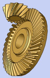
Bevel gear
The calculation is designed for geometric and strength designs and checks of bevel gear with straight, helical and curved teeth. The software gives solutions to the following tasks:- Calculation of helical and straight toothing.
- Automatic design of a transmission with the minimum number of input requirements.
- Design for entered coefficients of safety (static, dynamic).
- Calculation of complete geometric parameters (including corrected toothing).
- Calculation of strength parameters, safety check.
- Supplementary calculations (calculation of parameters of the existing gear, temperature rise, design of shafts)
- Support of 2D and 3D CAD systems.
- Calculation of helical and straight toothing.
-
Worm gear
The calculation is used for geometrical and strength designs and worm gearing check. The program solves the following tasks.- Calculation of gearing dimensions.
- Automatic transmission design with minimum input requirements.
- Design for safety coefficients entered.
- Calculation of a table of proper solutions.
- Calculation of complete geometrical parameters.
- Calculation of strength parameters, safety check.
- Gearing design for precise centre-line distance.
- Auxiliary calculations (heating, shaft design).
- Support of 2D and 3D CAD systems.
- Calculation of gearing dimensions.
-
Planetary gear
The calculation is designed for geometric and strength design and check of epicyclic gearing with straight and helical toothing. The application provides solutions for the following tasks.
- Calculation of helical and straight toothing.
- Automatic design of a transmission with the minimum number of input requirements.
- Design for entered coefficients of safety.
- Calculation of complete geometric parameters (including corrected toothing).
- Optimization of toothing by use of proper correction (balancing specific slips, minimizing specific slips, strength...).
- Calculation of strength parameters, safety check.
- Supplementary calculations (calculation of parameters of the existing gear, design of shafts, check dimensions).
- Support of 2D and 3D CAD systems.
- Drawings of an accurate tooth shape including data (X,Y coordinates).
-
Design of a transmission ratio
This workbook includes two auxiliary calculations to calculations of gearing.- Optimizing of parameters (dimensions, weight, volume) through distribution of the total transmission ratio "i" to individual pairs of gears with double reduction or triple reduction gearbox with spur gears.
- Optimizing of the number of teeth of gears to achieve an exact total transmission ratio "i" with single, double and triple reduction transmissions (toothed wheels, toothed belts, chains)
-
-
Belts and chains
-
V-belts
The calculation is designed for geometrical and strength designs of belt transmissions using V-belts. The application provides solutions of the following tasks:- Calculation for 2 or 3 pulleys.
- Automatic design of a transmission with the minimum of input requirements.
- Design and calculation of geometrical parameters (diameters of pulleys, axis distances, length of the belt, weight of the transmission)
- Calculation of strength parameters (power transferred by the belt, number of belts, efficiency, etc.)
- Calculation of force conditions (prestressing, axis loading of the pulleys, etc.)
- Support of 2D and 3D CAD systems.
 Manufacturers Association), ISO, DIN, BS, and basic documents from catalogues of companies CONTITECH® and Gates Rubber Company®. List of standards: Narrow V-Belts ANSI/RMA IP-22; Traditional V-Belts ANSI/RMA IP-20; Light Duty V-Belts ANSI/RMA IP-23; DIN 7753; DIN 2211; DIN 2215; ISO 4184
-
Toothed belts
The calculation is designed for a geometrical design and strength check of toothed belt transmissions. The application solves the following tasks.- Selection of the type of belt with a suitable output power.
- Selection of an optimum transmission alternative in view of power, geometry and weight.
- Option of designing a non-standard transmission.
- Calculation of all necessary strength and geometrical parameters.
- Calculation of power parameters and axis loads.

- Support of 2D and 3D CAD systems.
-
Roller chains
The calculation is designed for a geometrical design and strength check of common chain transmissions using roller chains.- The application solves the following tasks.
- Selection of a power suitable type of chain.
- Selection of an optimum transmission alternative regarding power, geometry and weight.
- Calculation of geometric, strength, safety and operational parameters.
- Calculation of power parameters and axis loads.
- Support of 2D and 3D CAD systems.
-
Transmission using multiple pulleys/sprocket wheels
The calculation is developed for geometrical designs of belt / chain transmissions with more sprocket wheels. The application provides designs for the following basic tasks.- Calculation of the necessary length of the belt (chain) using known positions and diameters of sprocket wheels
- Achieving the desired (table) length of the belt / chain using a change in the position of the selected sprocket wheel.
- Calculation of geometry (angles of wrapping, numbers of teeth in engagement, axis distances, etc.)
- Calculation of the radial force acting on the sprocket wheel axis.
- The application works with 2D CAD systems.
-
-
Ložiska
-
Roller bearings I - SKF, II - (Palcová) & III - (INA, FAG)
These modules can be used for the selection, calculation and check of rolling bearings. The software provides solutions to the following tasks:- Selection and check of a suitable bearing.
Roller bearings I - This module includes a database of approx. 10,000 different rolling bearings SKF in all basic types and design.
Roller bearings II - This module includes a database of approx. 5,000 rolling bearings from RBC Bearings, Nice Ball Bearing, General Bearing Company, New Hampshire Ball Bearing, NMB USA Inc., MRC Bearing Group, Fafnir Bearings Company, Torrington Company, Timken Company, Barden Precision Bearing, McGill Manufacturing Co. Inc., NTN Bearing Corporation and INA USA Corporation.
Roller bearings III - This module includes a database of approx. 5,000 different rolling bearings INA/FAG in all basic types and design. - Calculation of basic bearing parameters (life, static safety, etc.).
- Calculation of adjusted bearing life acc. to the new methodology of ISO 281.
- Calculation of load with a pair of tapered roller bearings or a pair angular contact ball bearings resp.
- Support of 2D and 3D CAD systems.
In addition to the above given basic calculations, the document also includes several other auxiliary calculations (e.g. a calculation of lubricant operational viscosity, calculation of mean loads for bearings loaded by variable loads, calculation of permitted bearing speed, etc.). The software uses data, procedures, algorithms and other information from specialized literature and catalogues of rolling bearings (Deep groove ball bearings, Angular contact ball bearings, Self-aligning ball bearings, Cylindrical roller bearings, Needle roller bearings, Taper roller bearings, Spherical roller bearings, Toroidal roller bearings, Thrust ball bearings, Cylindrical roller thrust bearings, Needle roller thrust bearings, Spherical roller thrust bearings), ISO, ANSI, SAE standards and other sources. Related standards: ISO 15, ISO 76, ISO 104, ISO 281, ISO 355, ISO 1132, ISO 5593, ISO 5753, ISO 3448, ISO 15312, DIN 615, DIN 620, DIN 625, DIN 628, DIN 630, DIN 635, DIN 711, DIN 715, DIN 720, DIN 722, DIN 728, BS 290, BS 292, BS 3134, ANSI/ABMA 9-1990, ANSI/ABMA 11-1990.
- Selection and check of a suitable bearing.
-
-
Tolerances, tolerancing
-
Tolerances
This workbook includes tables and calculations for easy option of fits of machine parts and determination of their dimensional tolerances and deviations. Using this tool the following tasks can be solved:- Selection of suitable fits of machine parts according to the international standard ISO 286.
- Determination of dimensional tolerances and deviations of machine parts according to the international standard ISO 286.
- Selection of preferred fits of machine parts and determination of their dimensional tolerances and deviations according to ANSI B4.1.
- Determination of non-prescribed limit deviations of linear and angular dimensions according to ISO 2768.
- Automatic design of a fit for the given clearance or fit interference respectively.

-
Tolerance analysis of linear, 2D and 3D dimensional chains
Two programs are available for the analysis of linear, 2D and 3D dimensional chains, which in addition to the basic analysis (Worst case, Root Sum Squares, Monte Carlo...) also include a solution to some special matters, like analysis of a dimensional chain deformed as a result of temperature change and design of tolerances for a selective assembly.Tolerance analysis of linear dimensional chains.
The program is designed for tolerance analysis of linear (1D) dimensional chains. The program solves the following problems:
- Tolerance analysis, synthesis and optimization of a dimensional chain using the arithmetic "WC" (Worst case) method, possibly the statistical "RSS" (Root Sum Squares) method.
- Analysis of a dimensional chain deformed as a result of temperature change.
- Extended statistic analysis of dimensional chain using the "6 Sigma" method.
- Tolerance analysis of a dimensional chain during selective assembly including optimization of the number of assembled products.
Tolerance analysis of 2-D and 3-D dimensional chains
The program is designed for the tolerance analysis of two-dimensional (2-D) and three-dimensional (3-D) dimensional chains. The program solves the following problems:- Tolerance analysis of a dimensional chain using the "Worst case" method.
- Tolerance analysis of a dimensional chain using the "Monte Carlo" method.
-
-
Connections
-
Bolted connection
The calculation is designed for a geometrical design and strength check of a prestressed bolt connection, loaded by static or cyclic loading resp., acting both in the axis of the bolt and in the plane of the connected parts. The application solves the following tasks:
- Automatic design of a connection bolt of standard design.
- Calculation and check of connections fitted with special shanks.
- Design and calculation of necessary mounting prestressing of the connection and fastening torque.
- Calculation of force conditions of a loaded connection.
- Static and dynamic strength check.
- The application includes a table of commonly used materials of bolts according to ISO, SAE and ASTM, and a selection of materials of the connected parts according to AISI/SAE, DIN, BS, AF and others.
- Support of 2D CAD systems.
-
Coupling of shafts using a key, grooving
The calculation is designed for geometric designs and strength checks of shaped couplings of shafts with hubs. The application provides solutions for the following tasks:- Design of a coupling with parallel side keys.
- Design of a coupling with Woodruff's keys.
- Design of a coupling with straight-sided splines.
- Design of a coupling with involute splines.
- Strength check of designed couplings.
- The application includes a table of keys and splines according to ISO, SAE, DIN, BS, JIS and CSN.
- Support for 2D CAD systems.
- Design of a coupling with parallel side keys.
-
Force couplings of shafts with hubs
The calculation is intended for geometrical design and strength check of force couplings of shafts with hubs with a cylindrical contact area. The application provides solutions for the following tasks:
- Design of force fits, possibly shrink fits.
- Design of clamping connections with separated, or one-side cut hub.
- Strength check of designed couplings.
- Check of interference fit strained by additional radial force with bending moment.
- Check of interference fit working at specific service temperature.
-
Pins and clevis pins couplings
The calculation is intended for the geometric design and strength check of couplings using pins and clevis pins. The program is used to solve the following tasks:- Design of pin for spring attachment.
- Design of couplings with securing pins.
- Design of cross pin in rod and sleeve.
- Design of radial pin for shaft-hub connection.
- Design of longitudinal pin for shaft-hub connection.
- Design of clevis pin for rotating rod-clevis connection.
- Strength check of designed couplings.
- The program includes dimensional tables for pins and clevis pins according to ANSI, ISO, DIN, BS, JIS and CSN.
- Support of 2D CAD systems.
-
Welded connections
The calculation is intended for the geometrical design and strength control of statically loaded welded connections of machine structures manufactured from carbon steels. The program enables you to design over 50 of the most common types of welded connections stressed by various combinations of load. The calculation deals with the following tasks:- Design of connections with butt welds.
- Design of connections with fillet welds.
- Design of connections with plug and slot welds.
- Design of connections with spot (resistance) welds.
- Strength control of designed connections.
- The program includes a table with approx. 700 carbon steels suitable for welding according to the material standards ANSI, EN, JIS, ISO, DIN, BS, NF, UNI, UNE, SIS, CSA, NBN, NP, NS, ON and CSN.
- The program also includes a dimensional table of steel sections S, ST, W, WT, C, L according to ASTM/AISI/AISC and T, I, U, L sections according to DIN/EN/ISO.
-
-
Springs
-
Compression spring
The calculation is intended for the purposes of geometric and strength designs of helical compression cylindrical springs made of wires and rods of circular sections, loaded with static or fatigue loading resp. In addition to the design of geometric and strength parameters, the calculation works with CAD systems. The application provides solutions of the following tasks:- Automatic design of a spring.
- Selection of an optimal alternative of spring design in view of strength, geometry and weight.
- Static and dynamic strength check.
- Calculation of working forces of a spring of known production andinstallation dimensions.
- Calculation of installation dimensions for known loading and production parameters of the spring.
- Support for Cold formed springs and Hot formed springs
- The application includes a table of commonly used spring materials according to ISO, EN, ASTM/SAE, DIN, BS, JIS and others.
- Support of 2D a 3D CAD systems.
- Automatic design of a spring.
-
Tension spring
The calculation is intended for the purposes of geometric and strength designs of helical tension cylindrical springs made of wires and rods of circular sections, exposed to a static loading. In addition to the design of geometric and strength parameters, the calculation co-operates with CAD systems. The application provides solutions of the following tasks:- Automatic design of a spring.
- Selection of an optimal alternative of the spring design in view of strength, geometry and weight.
- Strength check of the spring.
- Calculation of working forces of a spring of known production and mounting dimensions.
- Calculation of mounting dimensions for a known loading and production parameters of the spring.
- Support for Cold formed springs and Hot formed springs
- The application includes a table of commonly used spring materials according to ISO, EN, ASTM/SAE, DIN, BS, JIS and others.
- Support for 2D and 3D CAD systems.
- Automatic design of a spring.
-
Torsion spring
The calculation is intended for the purposes of geometric and strength designs of spiral cylindrical torsion springs made of wires and rods in circular sections, exposed to a static or cyclic loading. In addition to the design of geometric and strength parameters, the calculation works with CAD systems. The application provides solutions for the following tasks:- Automatic design of the spring.
- Selection of the optimal design of the spring with respect to strength, geometry and weight.
- Static and dynamic strength tests.
- Calculation of the working forces of a spring with known production and mounting dimensions.
- Calculation of mounting dimensions for known spring loading and production parameters.
- Support for Cold formed springs and Hot formed springs
- The application includes a table of commonly used spring materials according to ISO, EN, ASTM/SAE, DIN, BS, JIS and others.
- Support of 2D and 3D CAD systems.
- Automatic design of the spring.
-
Springs - 15 types
The calculation is to be used for geometrical and strength design of metal springs of various types and designs, subjected to static or cyclic loads. The program performs the following tasks:- Geometrical design and calculation of working cycle parameters for metal springs of the following types and designs:
- Helical cylindrical compression springs of round wires and bars
- Helical cylindrical compression springs of rectangular wires and bars
- Helical conical compression springs of round wires and bars
- Helical conical compression springs of rectangular wires and bars
- Belleville springs
- Helical cylindrical tension springs of round wires and bars
- Helical cylindrical tension springs of rectangular wires and bars
- Spiral springs
- Helical cylindrical torsion springs made of round wires a bars
- Helical cylindrical torsion springs made of rectangular wires and bars
- Torsion bar springs with round section
- Torsion bar springs with rectangular section
- Leaf springs with constant profile
- Leaf springs with parabolic profile
- Laminated leaf springs - Automatic proposal (finding) of a spring with suitable dimensions.
- Static and dynamic strength check.
- Geometrical design and calculation of working cycle parameters for metal springs of the following types and designs:
-
-
Tools and tables
-
Search for calculation, project
VMost of the calculations include a uniform header that:- Unifies the appearance and improves the orientation in printed outputs.
- Maintains uniform information on the performed calculations and enables their effective management.
- Enables fast retrieval of any calculation (project) using the delivered tool "Search calculation".

Searching of calculation
In case of more intensive use of calculations the volume of *.xls calculation files with various alternatives of solutions or files determinated for various project will be increasing. This tool is determinated for simple retrieval of a calculation and easy orientation among the calculation *.xls files and enables:- Searching through the complete directory structure including hidden sub-directories.
- Uploading of all pieces of information from calculation headers into a well-arranged table.
- Simple filtration and searching according to the entered parameters.
- Fast opening of the selected file / calculation.
-
Conversion of units, tables
MIn addition to all the calculations, MITCalc also contains many comparison and conversion tables.Conversion of units.
This table allows conversion of various units from various unit systems. It also allows conversions of a gearing (module, pitch, mm, inches), roughness, and material hardness conversions and material strengths. .
.Tables of safety coefficients.
Some commonly used theories and tables for determination of safety coefficients corresponding to certain design conditions.Comparison table of gears.
Self-contained information allowing quick selection of a suitable and optimal type of a gear with constant gear ratio.Comparison table of shaft connections.
When selecting a shaft connection type with a hub, this table may be very useful. It compares basic properties of particular connection types . -
Technical formulas
Excel workbook contains solutions to dozens of basic formulas from physics, technology and mechanical engineering. Help, pictures as well as many selection tables with values of various coefficients and material properties are available for the formulas. The following matters are solved in the workbook:- Characteristics of solids (volume, surface, weight, inertia moment)
- Rectilinear motion (speed, acceleration, trajectory, time, force, energy....)
- Rotation motion (speed, acceleration, trajectory, time, force, energy....)
- Thermal expansion (longitudinal, cubical)
- Friction (shear, rolling, journal, rope, belt)
- Design of engine capacity (pump, blower, hoist, crane)

Pozn: The standalone module includes a workbook with conversion of units and tables.
-